Visit the whole site at: http://borg20011.tripod.com/borg_link_o_rama.htm

CONTENT:
1- YEC parts catalog 2- Gearing changes charts 3- The back pressure myth
4- Shift-shaft problems 5- Temperature switch modification 6- Aluminum polishing
7- Headlights modulator url 8- Relay for 4 flashers with LEDs
9-How to install running lights or flashers in the front lights pods (updated)
10-02 R1 yellowbox install 11-Adjusting the air/fuel ratio on EFI R1`s
12-04 R1 yellow box install by Glenn Hall (GRH)
![]()
1
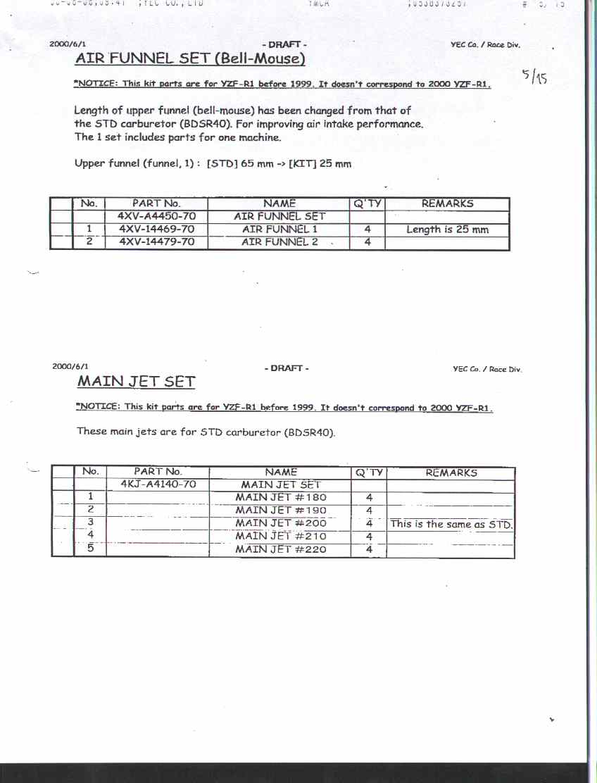
Some YEC parts pages (98-99 only):
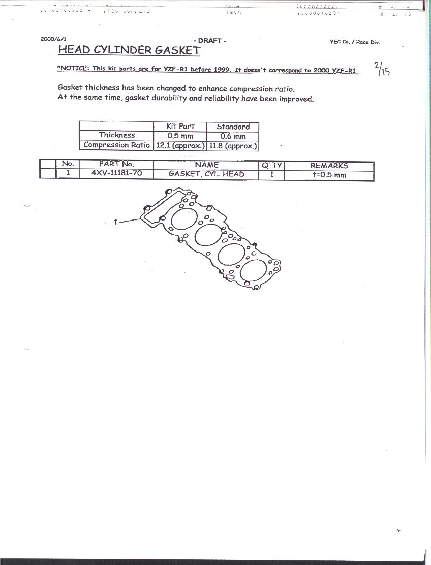
Head gasket: Click here
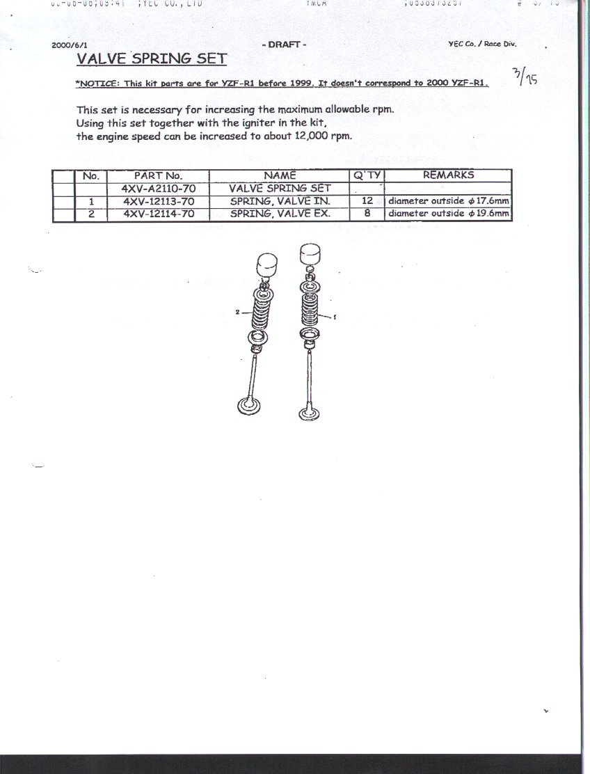
Valve springs set: Click here
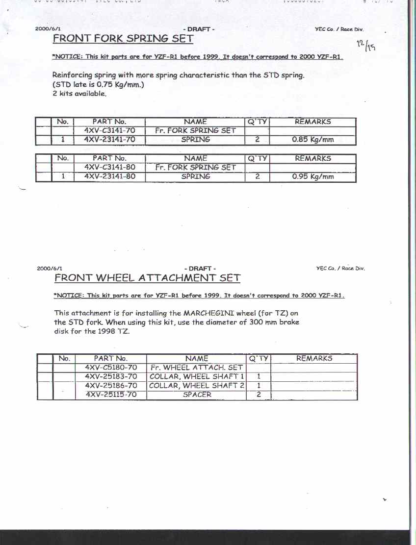
Fork springs and front wheel attachment: Click here
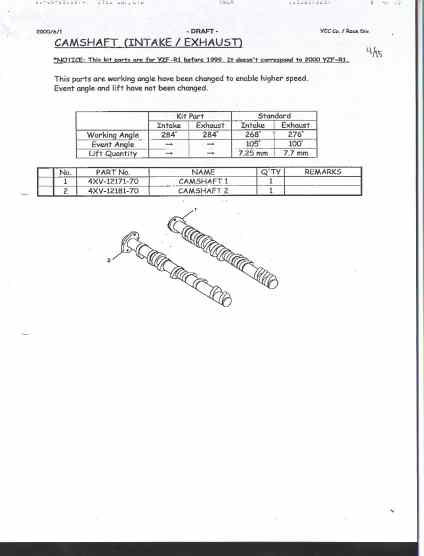
Camshafts: Click here
Velocity stacks and main jets: Click here
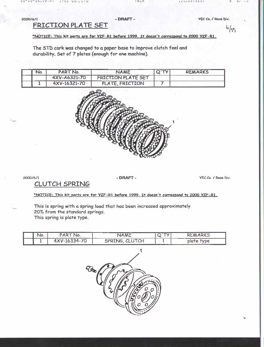
Clutch friction plate set and racing diaphragm: Click here
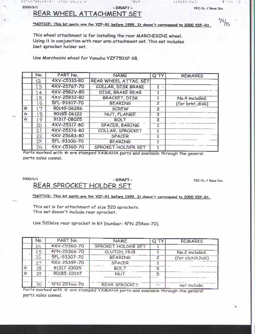
Racing cush-drive and rear wheel attachment: Click here
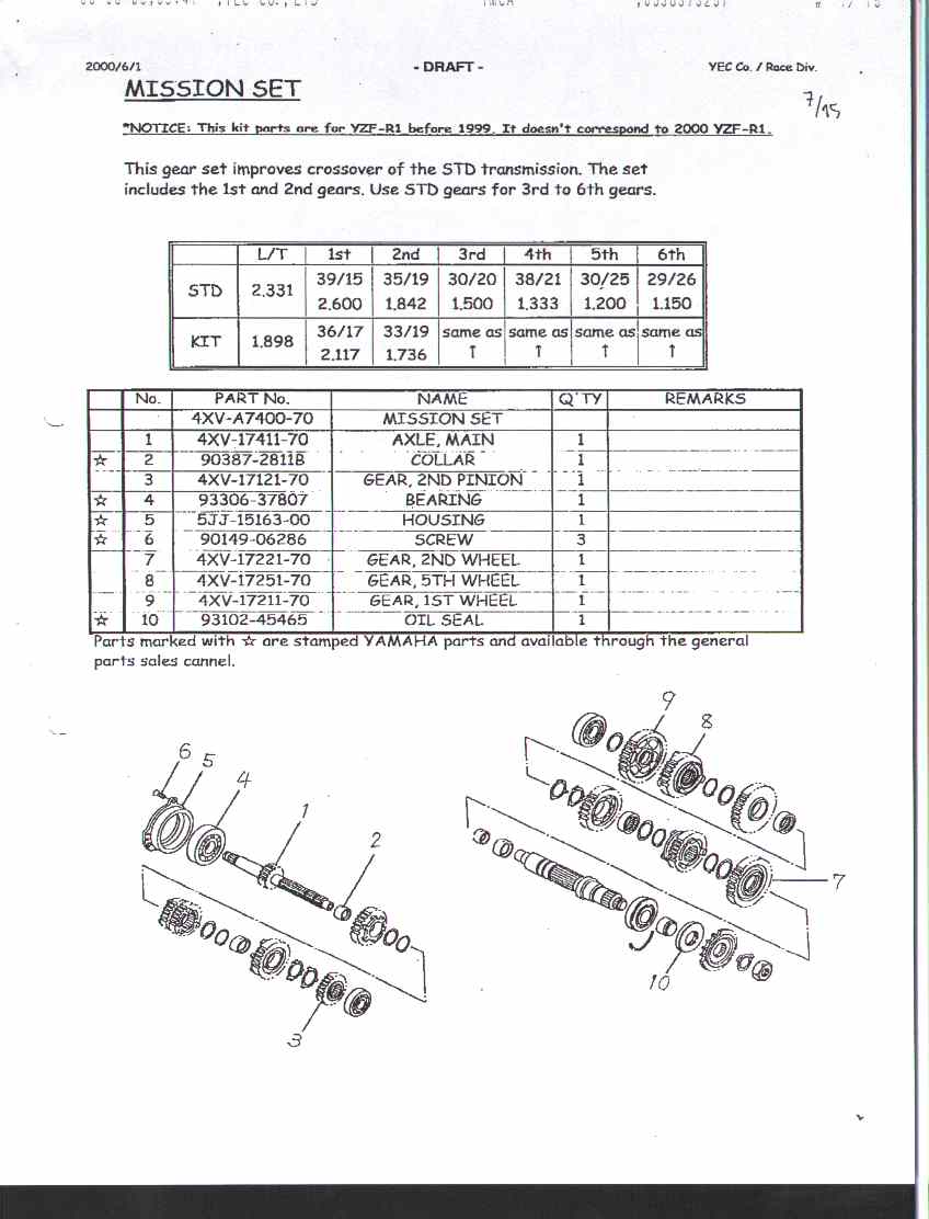
Racing transmission: Click here
Racing sprockets: Click here
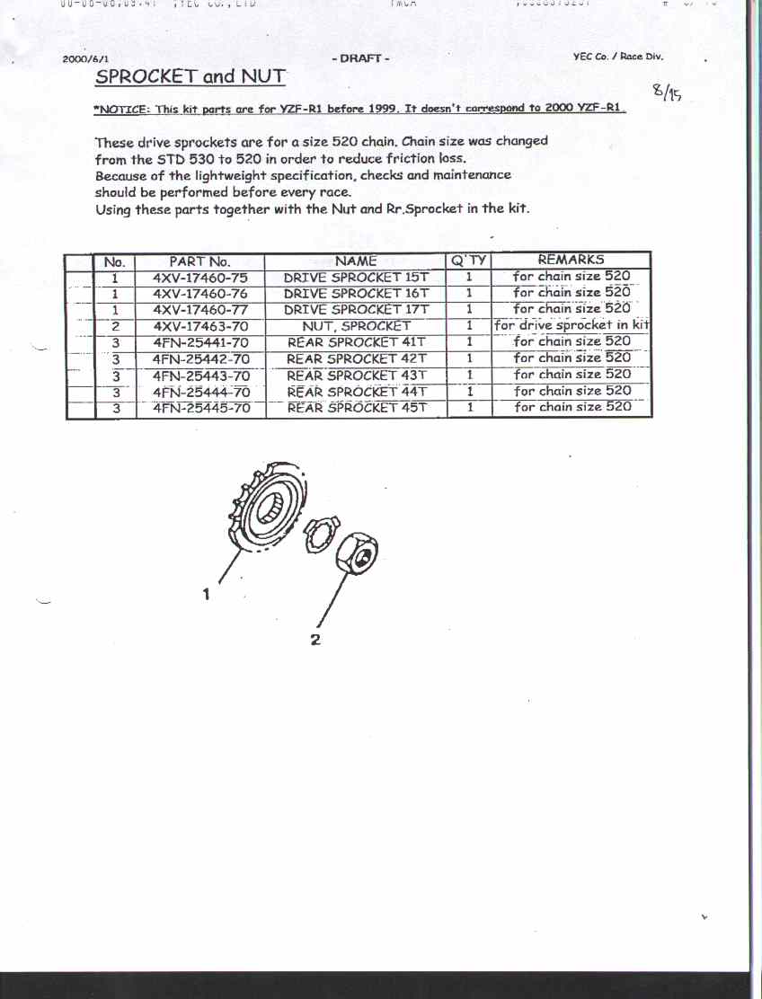
Racing harness and ignition box: Click here
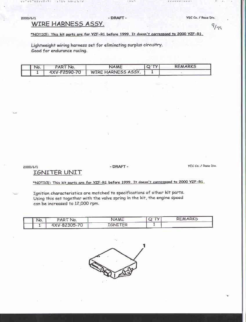
Rear arm attachment set parts list: Click here
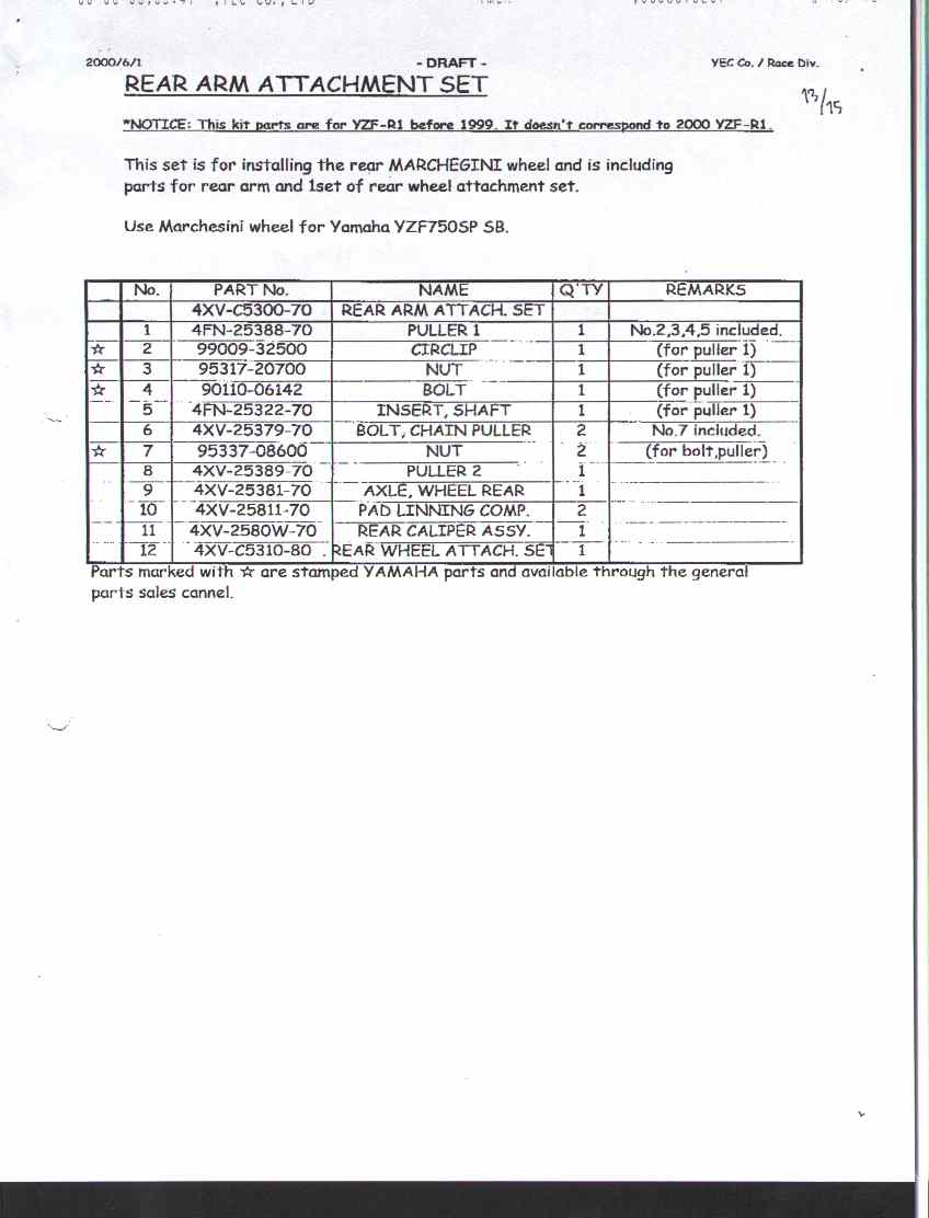
rear arm attachment set parts pictures: Click here
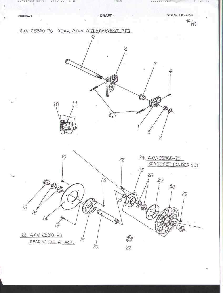
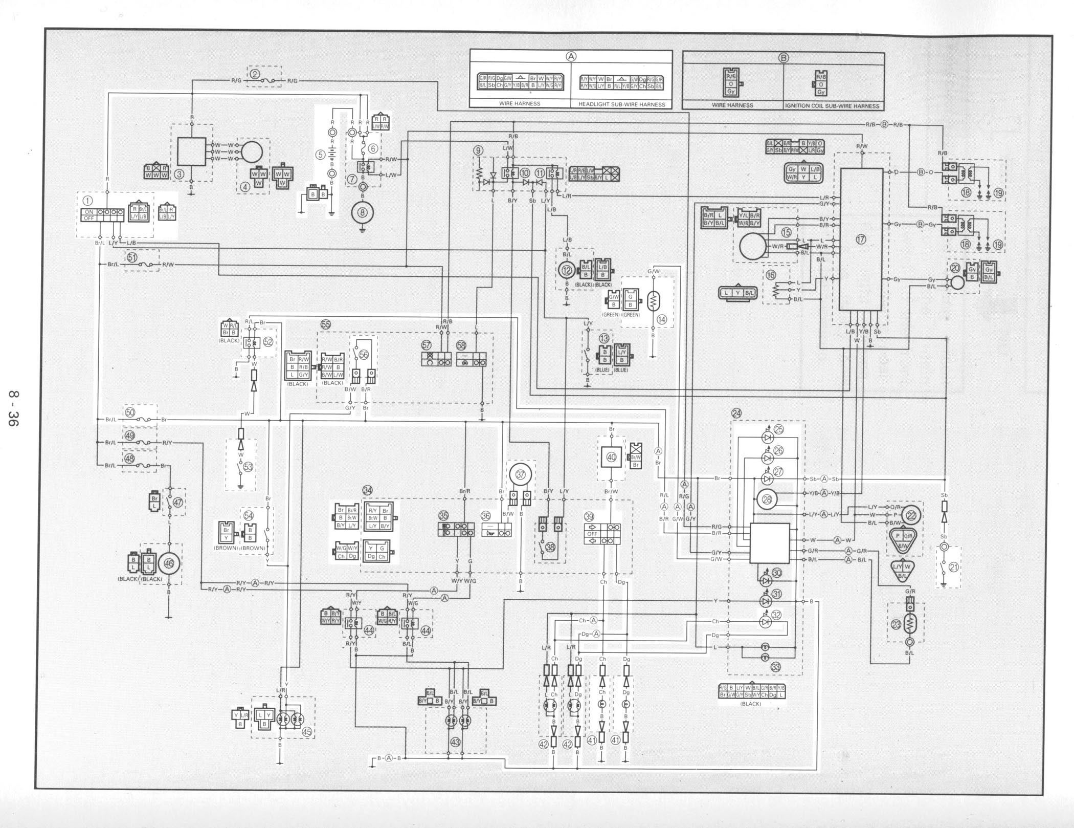
R1 wiring diagram: Click here
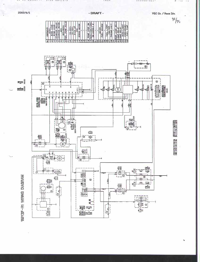
Quick-action throttle: Click here
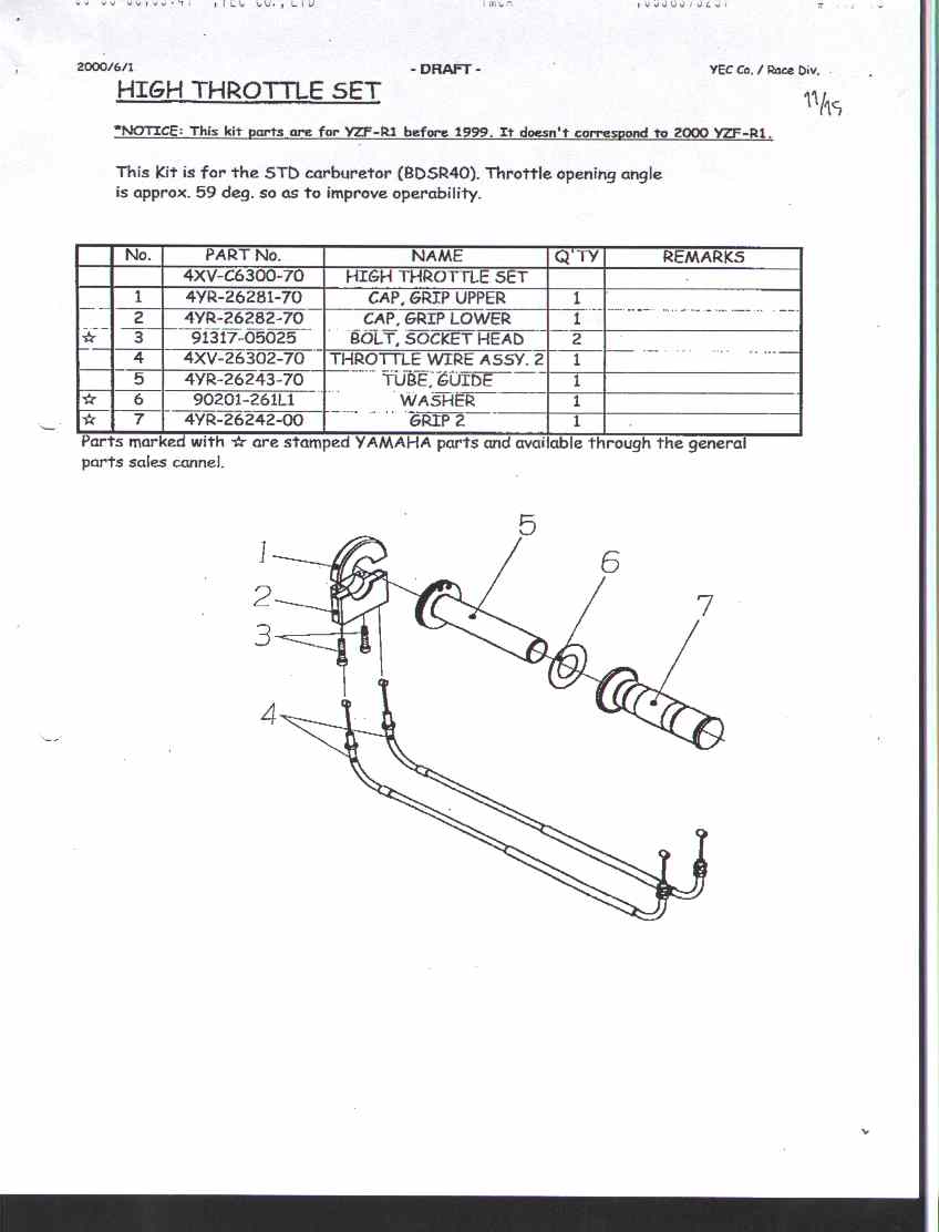
Some small parts specs: Click here
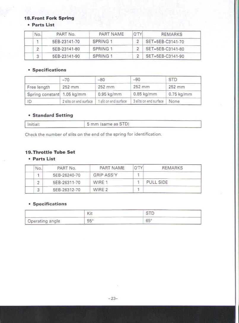
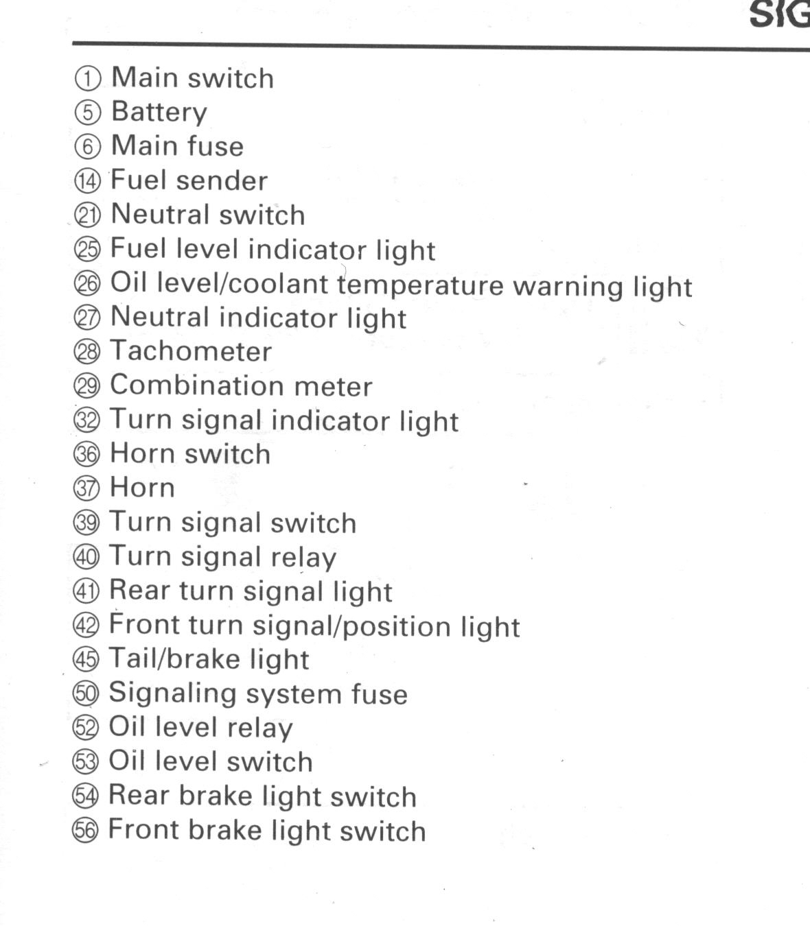
R1 signal schematic: Click here
R1 signal schematic keys: Click here
![]()
2
Gearing changes results
(km/h in black, mph in green)
(Rear sprockets swaps)
| Stock | +1 (44) | Loss | +2 (45) | Loss | -1 (42) | gain | -2 (41) | Gain | |
| 1st | 110 (70) | 108 (68) | -2 (-2) | 105 (67) | -5 (-3) | 113 (71) | +3 (+1) | 115 (73) | +5 (+3) |
| 2nd | 155 (98) | 151 (96) | -4 (-2) | 147 (94) | -8 (-4) | 158 (101) | +3 ( +3) | 162 (103) | +7 (+5) |
| 3rd | 194 (121) | 190 (118) | -4 (-3) | 185 (115) | -9 (-6) | 199 (123) | +5 (+3) | 203 (127) | +9 (+6) |
| 4th | 232 (136) | 226 (133) | -6 (-3) | 221 (130) | -11 (-6) | 237 (139) | +5 (+3) | 243 (143) | +11 (+7) |
| 5th | 268 (151) | 262 (148) | -6 (-3) | 255 (144) | -13 (-7) | 274 (155) | +8 (+4) | 280 (158) | +12 (+7) |
| 6th | 298 (162) | 292 (159) | -6 (-3) | 285 (155) | -13 (-7) | 305 (166) | +7 (+4) | 313 (170) | +15 (+8) |
(Front sprockets swaps)
| Stock (16) | -1 (15) | Loss | +1 (17) | Gain | |
| 1st | 110 (70) | 103 (65) | -7 (5) | 117 (74) | +7 (4) |
| 2nd | 155 (98) | 145 (92) | -10 (6) | 164 (105) | +9 (7) |
| 3rd | 194 (121) | 182 (113) | -12 (8) | 206 (128) | +12 (7) |
| 4th | 232 (136) | 217 (127) | -15 (9) | 246 (144) | +14 (8) |
| 5th | 268 (151) | 251 (142) | -17 (9) | 285 (160) | +17 (9) |
| 6th | 298 (162) | 279 (152) | -19 (10) | 317 (172) | +19 (10) |
The mph figures are off by a good 8%; use them as a reference only.
As much as I'd like to produce dyno charts to show the real differences between gearing setups,
that would require gears swap and I'm not eager to do it...lol
It sure would be interesting to see HP and torque curves movements though.
![]()
3
Exhausts back pressure and related info.
A lot of people have different thoughts on back pressure, and often confuse it with Velocity and Delta Pressure...
"THE MYTH OF BACKPRESSURE"
is probably the most widely misunderstood concept in engine tuning. IMO,
the reason this concept is so hard to get around lies in the engineering terms
surrounding gas flow. Here's the most important ones you need to be aware
of to understand the things I'm about to say:
BACK PRESSURE: Resistance to air flow;
usually stated in inches H2O or PSI.
DELTA PRESSURE (aka delta P): Describes
the pressure drop through a component and
is the difference in pressure between two points.
One other concept needs to be covered too, and that's the idea of air pressure
vs. velocity. When a moving air column picks up speed, one of the weird things
that happens is its pressure drops. So remember through all this that the
higher the air velocity for a given volume of gas, the lower it's internal
pressure becomes. And remember throughout all of this that Im no mechanical
engineer, simply an enthusiast who done all the reading he can. I dont claim
that this information is the absolute truth, just that it makes sense in my
eyes.
Ok, so as you can see, back pressure is actually defined as the resistance
to flow. So how can back pressure help power production at any RPM? IT CAN'T.
I think the reason people began to think that pressure was in important thing
to have at low RPM is because of the term delta pressure. Delta pressure is
what you need to produce good power at any RPM, which means that you need
to have a pressure DROP when measuring pressures from the cylinder to the
exhaust tract (the term "pressure" is what I think continually confuses things).
The larger the delta P measurement is, the higher this pressure drop becomes.
And as earlier stated, you can understand that this pressure drop means the
exhaust gas velocity is increasing as it travels from the cylinder to the
exhaust system. Put simply, the higher the delta P value, the faster the exhaust
gasses end up traveling. So what does all this mean? It means that it's important
to have gas velocity reach a certain point in order to have good power production
at any RPM (traditional engine techs sited 240 ft/sec as the magic number,
but this is likely outdated by now).
The effect of having larger exhaust pipe diameters (in the primary, secondary,
collector and cat-back exhaust tubes) has a direct effect on gas velocity
and therefore delta P (as well as back pressure levels). The larger the exhaust
diameter, the slower the exhaust gasses end up going for a given amount of
airflow. Now the ***** of all this tech is that one exhaust size will not
work over a large RPM range, so we are left with trying to find the best compromise
in sizing for good low RPM velocity without hindering higher RPM flow ability.
It doesn't take a rocket scientist to understand that an engine flows a whole
lot more air at 6000 RPM than at 1000 RPM, and so it also makes sense that
one single pipe diameter isn't going to achieve optimal gas velocity and pressure
at both these RPM points, given the need to flow such varying volumes.
These concepts are why larger exhaust piping works well for high RPM power
but hurts low RPM power; because is hurts gas velocity and therefore delta
P at low RPM. At higher RPM however, the larger piping lets the engine breath
well without having the exhaust gasses get bundled up in the system, which
would produce high levels of back pressure and therefore hurt flow. Remember,
managing airflow in engines is mainly about three things; maintaining laminar
flow and good charge velocity, and doing both of those with varying volumes
of air. Ok, so now that all this has been explained, let's cover one last
concept (sorry this is getting so long, but it takes time to explain things
in straight text!).
This last concept is why low velocity gas flow and back pressure hurt power
production. Understand that during the exhaust stroke of a 4 stroke engine,
it's not only important to get as much of the spent air/fuel mixture out of
the chamber (to make room for the unburned mixture in the intake system),
it's also important that these exhaust gasses never turn around and start
flowing back into the cylinder. Why would this happen? Because of valve overlap,
that's why. At the end of the exhaust stroke, not only does the piston start
moving back down the bore to ingest the fresh mixture, but the intake valve
also opens to expose the fresh air charge to this event. In modern automotive
4 stroke engines valve overlap occurs at all RPM, so for a short period of
time the exhaust system is open to these low pressure influences which can
suck things back towards the cylinder. if the exhaust gas velocity is low
and pressure is high in the system, this will make everything turn around
and go the opposite direction it's supposed to. If these gasses reach the
cylinder they will dilute the incoming mixture with un burnable gasses and
take up valuable space within the combustion chamber, thus lowering power
output (and potentially pushing the intake charge temp beyond the fuels knock
resistance). So having good velocity and therefore low pressure in the system
is absolutely imperative to good power production at any RPM, you just have
to remember that these concepts are also dependent on total flow volume. The
overall volume of flow is important because it is entirely possible to have
both high velocity and high pressure in the system, if there is simply not
enough exhaust piping to handle the needed airflow.
Its all about finding a compromise to work at both high and low RPM on most
bikes, but thats a bit beyond the scope of this post. All I am trying to
show here is how the term back pressure is in reference to a bad exhaust system,
not one that creates good low RPM torque. You can just as easily have back
pressure at low RPM too, which would also hurt low RPM cylinder scavenging
and increase the potential for gas reversion. And understand that these tuning
concepts will also affect cam timing, though that is again probably beyond
the scope of this post. At any rate, hope this helps, peace. "
Exhaust Scavenging
In essence, this is the opposite of the exhaust reversion described earlier.
Reversion: at the beginning of the intake
stroke during cam overlap, exhaust gas in the header is under high pressure
(negative delta P) and is pushed back into the cylinder, diluting the new
air/fuel charge.
Scavenging: at the beginning of the intake
stroke during cam overlap, the momentum of the exiting exhaust gasses creates
a brief vacuum (positive delta P) in the header, pulling out the remaining
exhaust gases from the combustion chamber, and allowing the new air/fuel charge
to be full-strength.
Scavenging is also the reason for differently shaped headers (4-2-1, 4-1)
and collectors. We use the momentum of exiting exhaust from one cylinder to
scavenge exhaust from another that is next in the firing order! The different
shapes allow for this to happen at different airflow velocities thus at different
RPM bands.
Scavenging takes advantage of the momentum of the exiting gasses. In essence,
the fast moving exhaust pulse pulls a vacuum behind it. Momentum is mass times
velocity. So not only do we need to keep the velocity high to prevent reversion
- but it greatly improves the scavenging effect.
Thus we have a balancing act. We want to minimize friction to lower the back
pressure as much as possible - larger pipes have less friction because they
have less surface area per unit volume. But we want to increase the delta
P as much as possible to prevent reversion and increase scavenging effects
- smaller pipes increase delta P because they increase velocity, hence
the tapered parts on high-quality exhausts systems; it's mainly an attempt
from the exhausts manufacturers to reach their goals of optimum delta-P and
scavenging effects...some are just better at what they're doing than others.
There are lots of tricks to try to widen the useful RPM band (stepped headers)
or to increase the overall efficiency (ceramic coated exhausts), but it's
still subject to this basic tradeoff:
Friction vs. Velocity
AKA: Back pressure vs. Delta Pressure
You want low friction and high velocity.
You want low back pressure and high positive delta pressure.
This is the truth, the whole truth and nothing but the truth...to those who keep saying that 4-2-1 are lesser systems that 4-1, I got to say...NICE TRY.
It may be true in some cases, but believe me, they are few. (the old Akrapovic vs. others)
But here are some more clarifications as well as a lesson in the EXUP valve (or other brands now) effect:
The goal of any exhaust system is
to efficiently remove burnt gases from the combustion chamber, prevent reversion
at overlap, and by enhancing exhaust gas velocity leaving the chamber, create
a vacuum to help draw or scavenge in more intake charge volume at cam overlap.
The key is maintaining exhaust gas velocity or energy as the gases leave the
exhaust port when the exhaust valve opens.
So as the exhaust gas leaves the exhaust port in a 4 stroke engine , it creates
a series of pressure waves traveling at the speed of sound that move towards
the exhaust tip (or forwards) and then some reflects back. Like the water
waves coming onto the beach, forward and back, forward and back. The main
overall direction is forwards but there is some reflection back to the exhaust
port (reversion).
Simple enough...everyone knows this. So what's new and groovy?
The problem is at cam overlap (when both the exhaust valve and intake valve
are both partially open and when the pressure in the chamber is greater than
in the intake port).
If a high pressure wave is reflecting back and arrives at the exhaust port
at the wrong time (i.e. when burnt gases still need to leave), it blocks the
flow out. You see these instances when a high pressure wave is reflected back
at the wrong time as dips in the torque curve AT REGULAR INTERVALS (usually
in the midrange rpms).
If a low pressure wave is reflecting back at the correct time at the exhaust
port it actually helps pull burnt gases out of the chamber and also helps
pull in more intake air/fuel at overlap. You see these favorable low pressure
reflected waves occurring on your torque curve as small torque increases AT
REGULAR INTERVALS.
Now here's the first bone of contention and a source of debate between exhaust
makers.
1. Is a reflected high pressure wave always bad?
Most of the experienced people I speak to say YES! You never want back pressure
and you want it as low as possible for as long as possible. The low back pressure
assists in maintaining that high exhaust gas velocity. They then design anti-reversion
chambers and/or place steps (increases in diameter at various proprietary
points along the length of the header) to prevent the reflected waves from
traveling back to the head. (tapered pipes?)
There are also some pretty smart people who believe slightly differently ...They
believe that if you have a high pressure reflected wave arriving a few milliseconds
before exhaust valve closure, you prevent the loss of intake air/fuel out
the exhaust valve at cam overlap. The exhaust back pressure at this crankshaft
degree in the exhaust stroke prevents leaking out or bleeding out of you intake
charge into the header and ensures all of it goes into the chamber for combustion.
However, these people do NOT use the exhaust diameter as a way to create this
back pressure. That would be too crude or less precise, since the back pressure
would exist at all times and they only want this back pressure over the few
crankshaft degrees when the exhaust valve is just about to close ,when the
intake valve is opening further, and the piston has reached TDC and starts
downward for the intake stroke. Using an exhaust just to have back pressure
then is like cutting butter with a chain saw.
The people who agree with this will often tell you that combustion chamber
and intake port pressures are higher than the pressure in the exhaust just
before exhaust valve closure . So some intake flow into the chamber can get
pushed out the closing exhaust valve by the higher combustion chamber pressures.
So all you guys that say back pressure is a good thing...I don't believe so...not
at all crankshaft degrees which is what you get with a restrictive diameter
exhaust. You don't want to have too big a diameter (actually it's cross-sectional
area) that will slow or kill velocity or energy. But no back pressure most
(99%) of the time is good.
2. How do we get low pressure waves and high pressure wave to arrive at the
correct time?
The conventional way to get the exhaust gas harmonic to do this dance of low
pressure to pull in more intake charge and high pressure to prevent bleeding
off all at the right time is by changing the tube layout on the header: using
lengths, diameters, collectors with various merge angles. But these are limited
to one harmonic or exhaust gas speed.
So some Japanese engineers at Yamaha (figures, it's always some genius engineer
at some bike manufacturer that comes up with these wild ideas) thought: "What
if you have an exhaust throttle valve (located in the header collector or
at the entrance to the secondary tubes in the first merge collector) that
could control the pressure wave behavior?".
The throttle valve angle would vary as the speed of the exhaust gases changed
to control the reflected waves. In an 11,000 rpm bike, the valve opens progressively
as the rpms climb as the tubes are "in step" with the engine harmonics and
less reflected waves occur but at around 7000 rpm, the valve is closed down
to 40-60% of wide open when the harmonic is "out of step" with the engine
and at 8500 rpm the exhaust throttle valve is progressively opened. How much
to change the throttle angle is based on crankshaft angle input or ignition
signal input to an ECU with then controls the throttle valve angle knowing
the harmonics of the engine. Now how an ignition trigger will affect this,
I'd need to write a whole chapter...or consult SAM...hehehe
We see these in the Mercedes McLaren F1 car. If you think this is somebody's
Frankenstein pipe dream then guess again. The new Suzuki GSXR1000, Honda CBR`s,
and Yamaha R1 already have these. And those are today's street bikes! The
impetus will not be performance oriented but the drive to bring this to the
market place will likely be more practical, as this throttle valve (the first
one was called the Exup or Exhaust Ultimate Power by Yamaha in the late 80's)
gains better emissions and lower exhaust noise.But
who really cares, we want mondo power,
so let's ditch those for aftermarket systems.
So the new toy for exhaust makers will be like variable valve timing and variable
cam timing...the mating of electronics to optimize exhaust harmonics at each
rpm as the harmonics change with the rpms climbing. It won't be just cut and
try any longer...it will be cut try and reprogram. Welcome to the new millennium.
"
It's coming...fuel injection (most 2002 flagship bikes), variable cam timing (VFR800),re-programmable ignition (aftermarket), tunable chassis (available on some bikes to some extent right now), semi-intelligent suspensions (we've been dreaming about those for some time now), and responsive compounds tires are right on the corner.
How about auto-variable length exhaust
systems?
![]()
4
Shift-shaft problems.
I forgot to take the name of the writer of this to give him credit...my bad. It's a personal experience tip;you may want to check the shift return spring before ordering/freaking out.
"I endurance race my R1 and
one part that fails is the shift shaft. So far it has failed twice in the
exact same place and I know of at least one other racer who has had the same
problem (he had a spare the first time mine failed). I'm not sure if you're
experiencing the same thing but it sounds very familiar. What happens is one
of the tabs that holds the spring on the ratchet that engages the shift drum
cracks and breaks. When this happens the shifting mechanism no longer functions
and the bike will fail to shift or jump out of gear since nothing is positively
holding the shift drum. It starts out with missed shifts and progresses until
you can't shift at all.
Fortunately it is a relatively cheap part (~$50) and it is very easy to
replace. You just take off the cover and pull it out and slide the new one
in.
![]()
5
Temperature switch modification (or swap).
This is taken from one of the boards I'm currently on; credit goes to a guy nicknamed "Hammer".
In case anyone is interested. Doing some research, I found some other motorcycle people(st1100, concourse, magna) who had changed their fan control switches. I found a part number for a switch from Wells. The number is SW504. AutoZone sells this switch so I went and purchased one for $16. Low and behold it screws right in to my radiator. The turn on temp is 92c compared to the OEM turn on temp of 105c. It shuts off at 87c. This should keep our bikes running right at around 90c went we are idling in traffic.
A little more research has cross referenced this switch to these other
brands:
Borg Warner: TFS500 (I'd buy this one, lol)
Facet: FS8404
Filko: TFS-1
Four Seasons: 35934
Don't hold me responsible if the cross referenced units
don't work.
There is only one slight problem if you want to use this switch. You
will have to create two small jumper wires or cut off the stock connecter
and replace with a different connecters. The Wells SW504 has two round
terminals coming off compared to our OEM blade style connecters. Making two
small jumpers with a female round connecter on one end and a male blade
connecter should be sufficient to get this up and running.
I hope this info has been useful to someone out there.
Hammer
Like the man said, do your homework before taking these as gospel;
they are pointers that can truly be gospel though!
![]()
6
Frame, Pipe, Aluminum Polishing - By Dean Germain
Polishing your bike can be easy if you follow the correct steps
to make it simple for yourself.
I will detail the steps and equipment needed to polish your frame and swingarm.
I will also give you a list of materials needed to complete the job as well as a few places to purchase these
items. Good luck with your
project.
Materials Needed:
-You will need a buffer. I recommend a Sears/Craftsman 6in. Sander/Polisher
model 91052.
This is a very inexpensive buffer. The buffing process can be rather harsh
on a buffer so I don't recommend
using a $200 Porter Cable.
The Sears buffer is only $50 and does the job very well.
-Spiral Sewn Buffs
-Loose Section Buff
-Emery Compound
-Tripoli Compound
-White Rouge
-Buff Rake
-Easy Off Heavy Duty Oven Cleaner
-Ear Plugs and Safety Glasses
-Mothers MAGS and Aluminum Wheel Polish
Here are the manufacturers, part numbers, and prices for the
buffs and compounds.
The rest of the items can be purchased at various local stores.
The phone numbers can be found online at each of the manufacturers homepages.
Eastwood Products product parts# and prices:
Spiral Sewn Buffs 13034: $5.99
Loose Section Buff 13043: $5.99
Emery Compound 13134: $4.99
Tripoli Compound 13135: $4.99
White Rouge 13001: $5.99
Buff Rake 13120: $9.99
http://www.eastwoodco.com/
Caswell Products product parts# and prices:
Spiral Sewn Buffs SSCW65: $5.00
Loose Section Buff LCW65: $5.00
Emery Compound BLKBC7: $7.00
Tripoli Compound BRBC7: $7.00
White Rouge WBC7: $7.00
Buff Rake WR995: $9.95
http://www.caswellplating.com/
The Process:
We are now ready to get started on our polishing.
The first thing we need to do is to remove any
body panels that we do not want
to get broken, screwed up, or polished. I removed everything from my bike including the rear sub-frame. I did, however, leave the
swingarm on the bike when I polished it. You can remove it if you like. I will not make a difference. The next thing that we need to
do is to mask off everything that will not be removed from the bike. We do not want to get any over-spray onto the remaining
parts of the bike. I just used masking tape and newspaper. I suggest putting several layers of newspaper so that the oven cleaner
does not soak through.
Now that our work area is clear, we are now ready to start stripping the anodized
finish off of the work area. I highly recommend
wearing safety glasses from here on. Start by spraying the oven cleaner on the work area. Try to spray close to the area as to
prevent over wetting your newspaper. Let the oven cleaner sit on there for about 20-30 minutes. Wipe off the oven cleaner with a
wet sponge. Now reapply a coat of oven cleaner to the work area. Now the work area should start to turn black. Once it has turned
black, you can wipe off the oven cleaner. Check to make sure that all of the work area is black. If there are spots, then you need to
reapply the oven cleaner to those areas to get the anodizing all of the way off. The areas that still have an anodized finish will not
polish. Now that our work area is free of any anodized finish, we are ready to start polishing.
Install a spiral sewn buff onto you buffer. I had to use two washers on the bottom of the buff to be able to crank the buff on really
tight to the buffer. You will not want the buff to spin on the shaft of the buffer. I also recommend leaving the handle off of the
buffer as this will just get in your way. We will start with the Emory compound first. This is a rather abrasive compound. We will
apply this to the buff. I recommend putting in earplugs now as the buffing process is quite loud. Turn the buffer on and lock it in at
the fast speed. Now take the Emory compound and apply it to the buff. By holding it against the surface of the buff, it will start to
melt onto the buff. We can now start buffing. Hold the buff against the surface of the work area. Use a little pressure,
but not too much as we want the buff and compound to do the work. You will start to see the black disappear from the work
surface. You are actually starting to buff the work material now. You will begin to see results in no time at all. I suggest moving
back and forth in a slow even motion so you do not heat the metal too much and cause imperfections in the final look. If you are
leaving a residue of compound on the work area then you are using too much compound. Be sure to rake your buffs every few
minutes to keep them clean. Once the buffs have filled with metal, they will buff very slowly and will be gray and hard. It is time to
replace the buff at that time. Continue buffing all of the surfaces until they are smooth and appear polished. Even though the work
area will appear polished, it will not be as appealing in the sunlight as it will if you finish the process. The second step is very
similar to the first step except for the compound. We will now need to switch to the Tripoli compound. This is a less abrasive
compound as the first and this process should not take near as long. Follow the steps as before, once again letting the buff do the
work. This will help to remove most of the scratches that the first step has left in the metal. Your work area should now really start
to luster. We are very close to finishing the project. The next step is to clean any of the compounds that may have built up from
the buffing process. I recommend using Mothers to clean this residue off. We do not want any residue built up that can scratch
the surface again. The last step is to remove all of the fine scratches from the work surface. This process is the easiest, but the
compound is the hardest to use. We will use the loose sewn buff and the White Rouge. The hard part is the fact that we are using a
loose sewn buff so it is hard to get the compound onto the buff. Once it is on though, you will just lightly apply this to the work
surface. This will remove any final scratches left by the first couple of steps. You will be able to keep your work looking nice by
cleaning it with the Mothers. This process does not have to be done all of the time.
The finish will be quite resilient once the polishing is done.
By Dean Germain.
Here are some links for those that are polishing their Frames/swingarms/wheels.
http://www.sportbikeguy.com/garage.html
![]()
7
Headlights modulator; this could be of help for those doing a lot of highway riding.
http://www.kisantech.com/path.html
![]()
8
Relay for 4 flashers with LEDs.
Ok, we all know about the Tridon CL12 for the incandescent flashers; but that just doesn't plain work with leds
flashers, making them flash at a rate of over 100 flashes/minute.
Instead, you got to go with the model Tridon EP37 electronic flashers relay which flashes at a rate of 60
flashes/minute...but its not easy to find; if you cant order it, you can always go with the more widely available
Federal Mogul electronic flashers relay #7216 which flashes at a rate of 90 flashes/minutes...still a bit fast, but
acceptable.
![]()
9
02 R1 yellowbox install by CrazyR1.
With pics!!!
http://www.yzf-r1forum.com/yellowbox.html
![]()
10
Hard starting?
On carbureted bikes: Use #17.5 pilot fuel jets and re-calibrate the mixture screws accordingly.
On EFI bikes: Re-program the idle or low rpms mapping a bit richer using an EGA.
This could be done with a PC3 or through the dash cluster.
![]()
11
Adjusting air/fuel ratio on an EFI R1.
Courtesy of Mark from the http://www.r1-forum.com
1) Coming out of the ECU is a yellow wire with a red lead.
(If it looks like there are two, don't worry. It is the same wire doubled back on itself in the loom.) Ground it.
2) While holding the Select and Reset buttons down at the same time, turn the ignition key to ON. Wait approx. 8 seconds.
3) The Diagnostic window should come
on with a "CO" code. Beneath it should be a indicator for Cylinder
#1, maybe "Cyl 1," and a number value.
That number value represents the factory setting for the air/fuel mix in Cylinder
#1. Use the buttons to richen or lean out the cylinder.
The dealer recommends richening it 3-5 steps to start, i.e., if it reads 7,
richen it to 10-12.
4) Select the next cylinder. Very likely
the factory settings are staggered, so if Cylinder #1 was 7, this one may
be 10. You don't want
to change the stagger. But you do want to richen each cylinder equally. So,
if you added 3 to Cylinder #1, add three to Cylnder #2.
This gives you a new Cylinder #2 setting of 13.
5) Repeat for each cylinder.
6) Turn ignition OFF.
7) Remove ground.
For those of you who know about carburators,
this mod is the same as adjusting your air/fuel screw on your carburators.
It would be a good idea to write down all the factory settings, in case you
want to change back.
I've tried to be clear. I am writing from an amateur's point of view. I am not a mechanic. But I am going to try this mod on my bike.
P.S. According to my dealer, this is
really the only adjustment that you can make to the air/fuel mix without a
Power Commander
(unless you are some sort of factory race team mechanic).
Note from martinc: Make sure to write down factory settings before attempting this procedure...
![]()
12
Yellowbox installation on a 04 R1
Huge thanks to GRH for this one (again!)
http://www.r1-forum.com/forums/showthread.php?s=&threadid=78340
![]()