Visit the whole site at: http://borg20011.tripod.com/borg_link_o_rama.htm

Page 1.
This site is mostly R1-related and under perpetual construction!
Click on the blue underlined links
![]()
Content:
1-Speedo mods 2-Levers info 3-Small tips and torque specs 4-Weight saving 5-Spring rates
6-Rear ride height 7-Cheap rearsets 8-Can a frame be repaired?
9-Clutch boss retaining ring removal procedure. 10-Swingarm bearings part#
11-Marchesini bearings part #
![]()
Here are a few pics of stuff frequently asked by many:
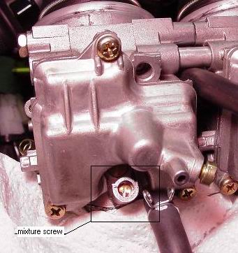
Mixture screw pic: click here
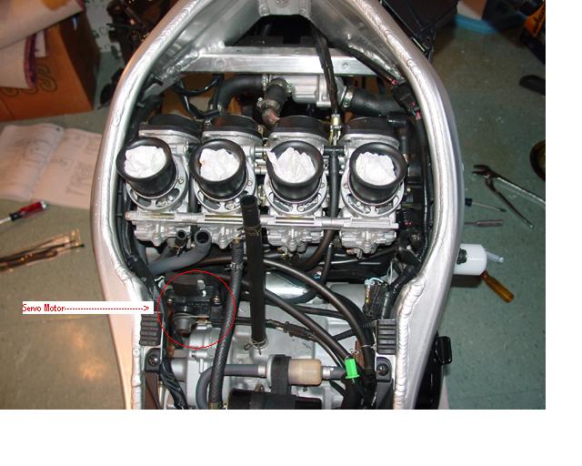
Servo-motor location: click here
Address of a site where you can see a walk-through
of going down under the tank!
http://www.carlspages.freeola.com/
Safety-wiring site and more:
Break-in procedure
Note: Leave the car motor oil aside (bad idea) and respect at least 4 heat-cycles the first day.
Heat cycles are done by starting the bike at the dealer, running it till it reaches
operating temp than shutting off till just warm (i.e. room temperature); repeat 4 times.
Recalls done to our bikes to this date:
![]()
1
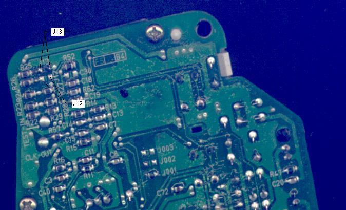
How to make a Canadian speedo (or any other)
function like an American model (mph or kph):
Details:
Open mean you don't touch anything; closed mean you have
to build a jumper between the 2 points shown.
If you want a UK specs speedo:
To be able to toggle between mph/km/h, with the odometer/trip meter reading
in miles and degrees centigrade temp:
J12-open
J13-close
If you want a USA specs speedo:
To be able to toggle between mph/kph, with the odometer/trip meter reading
in miles and degrees Fahrenheit temp:
J12-close
J13-open
If you want CANADA specs speedo:
Not able to toggle between mph/kph (reads only in kph).
odometer/trip meter only in kilometers.
degrees Celsius temp only.
J12-open
J13-open
![]()
2
Brake/clutch levers info:
Warning:
The 1998 and 1999 clutch and brakes levers DO NOT interchange;
It is dangerous to use the brake lever from another model year as
this can result in front brakes locking on you (worst result) or in
slightly constant-trail braking (bad for the pads/discs).
Note: As far as the clutch levers goes, they simply do not interchange at all; careful when ordering levers overseas, mention this.
![]()
3
Small tips:
Wheels valves stems:
Get the 90 degrees bend valves stems; no more dirty hands from rubbing
the discs or sprockets.
Shift-shaft return spring: part#YA90506-14002-00
Non-slipping clutch: add a second stock spring diaphragm
over the existing one; the lever is very hard, but the clutch cable
is lasting so far, and clutch life is amazing: over 40000km so far!
Note: A couple of years back, there was a psychosis about the infamous piano-wire found inside the clutch
basket (which retains the last plate); some called for the removal of it, which in some cases leads to plates
breakage; keep it there, I got a high-horsepower/high-mileage clutch to prove it.
Brighter tach/speedometer lights(98-99):
YAMAHA part#42X-83517-00-00
HONDA part#34908-mbo-003(UNTESTED)
Replacement of the stock ball-bearings forks bearings:
97 SUZUKI GSXR750/600 will fit part#SSS903(not sure of part#,but they do fit)
Popular stock forks modifications:
1-Change for 9.0 springs
2-Change for 7.5 weight forks oil
3-Adjust oil gap to 15-20mm
Exhausts sealer:
To lessen to popping under deceleration:
YAMABOND 6S (Yamaha stuff)
Torque specs:
Most torque specs are in the service manual, pages 2-18 through 2-22.
Calipers bolts:29ft-lbs
Headers bolts:14ft-lbs
Front axle:52ft-lbs
Rear axle:110ft-lbs
Countershaft sprocket:61ft-lbs
Swing arm nut: 80ft-lbs
Exhaust bolts (in frame): 14ft-lbs
Rear sets bolts: 27ft-lbs
Countershaft sprocket plastic cover: 7.2ft-lbs
Rear sprocket nuts: 52ft-lbs (may be an error in manual-this is good
Top triple clamps center nut: 85ft-lbs
Upper ring nut: 6.5ft-lbs
Lower ring nut: 21ft/lbs
Clipons pinch bolts: 13ft-lbs
Top triple clamp pinch bolts: 17ft-lbs
Bottom triple clamp pinch bolts: 17ft-lbs
Clipons positioning bolts: 9.5ft-lbs
Brake and clutch lever assemblies: 9.5ft-lbs
Bar ends: 3ft-lbs
More to come on rainy days!
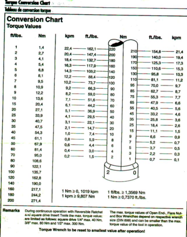
For a useful torque values conversion chart: click here
![]()
4
Weight savings in a quick view:
Did you know that replacing the stock ABS bodywork on your bike can shave as much as 15 lbs?
QbCarbon bodywork shave exactly 13 lbs without replacing the tank! An additional 7 lbs can be shaved
with the addition of a carbon tank!
![]()
5
Suspensions spring rates info:
Note: All data taken from Race Tech site.
Stock figures:
Forks: .750kg/mm
Shock: 8.0kg/mm
Recommended spring rates per riders weight. (Unclad rider)
Note: keep in mind that the left figures are for a preference for hard stiffness, the right one for std stiffness.
165lbs rider:
Forks: .910kg/mm .845kg/mm
Shock: 7.50kg/mm same
175lbs rider:
Forks: .925kg/mm .850kg/mm
Shock: 7.5kg/mm same
200lbs rider:
Forks: .963kg/mm .898kg/mm
Shock: 7.5kg/mm same
Note: See how interesting it is? As we go down on shock spring rates (but still the same value for our 3 virtual
racers), we are going dramatically up for the forks spring rates! What can we get out of this, class?
The gold valves make the shock stiffer and the stock R1 fork springs are shit! 10/10!!!
![]()
6
Rear ride height info:
If you raise the rear ride height by 15mm:
-reduced rake by 0.6 degree
-reduced trail by 3.6mm
Note: Measured with bike straight, no rider on it.
![]()
7
Build rear sets with your stock pegs:
Whether you've crashed or don't have the money to treat yourself (or your bike)
with rear sets, here are links and tips to transform the stock pieces:
Get jack up plates from: NWS
Get custom levers and folding separately from: MFW
Get rigid pegs from: OEM
![]()
8
Is it possible to repair badly dented frames?
Looks like yes, it is possible in the right hands!
Click on images to see the process
![]()
9
YZF-R1 Clutch Boss Retaining Ring Removal
Also known as the dreaded clutch "piano wire", this little thing as a tendency to break, leading to the back
friction plates also breaking with pieces flying inside the transmission and about everywhere else.
Text and pics courtesy of SANTO JANNOTTI.
Note: I do not recommend taking the system out; this is not a retrofit kit type of device
and in my opinion, adding an extra plate does not make for a perfect fix; I've heard
stories about plates breaking from the lack of this exact system on numerous R1;
proceed at your own risks if you really want to try, but I'm not pushing anyone.
Introduction
In an effort to reduce engine noise due to low-speed clutch chatter, Yamaha has incorporated a dampener assembly in the design of the clutch. The effectiveness of this device is debatable, and it has a downside to it....The dampener assembly consists of a beveled steel spring, a steel seat for this spring, a single friction plate with the same thickness and outer diameter as the rest, but with a larger inner diameter, and a single friction plate. The dampener assembly is secured to the inner clutch hub or "Boss" by a retaining ring that is made of spring steel, also known as "Piano wire". This steel wire is held in a groove that goes all around the circumference of the clutch boss, and is secured by forcing both ends through a single hole in the side of the clutch boss. This wire is under constant pressure and tension from the force of the bevel spring pressing up against the steel plate, and with the motor running, centrifugal force also tries to pull it from it's resting place. The faster you spin the motor, the harder that wire tries to come out of it's groove. Sadly, it sometimes succeeds in doing this, and the consequences of this event happening are usually catastrophic. Thankfully, you are NOT required to play "Russian Roulette" with your motor if you do not want to. The instructions below will show you how to remove both the retaining ring and the dampener assembly from the R1's clutch assembly.
Santo Jannotti
Step by Step Instructions
Step #1
After first removing the clutch cover from the engine, start by loosening the six bolts that hold the clutch diaphragm spring in place. Loosen them 1/4 turn at a time, using the star pattern shown, until all tension is removed. You can then remove them all the way, and lift off the diaphragm spring & it's seat.
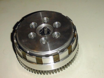
Step #2
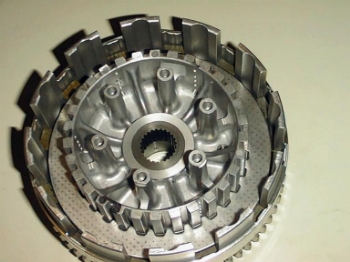
After removing the six bolts, the pressure ring, and the clutch diaphragm spring, your clutch will look similar to this. Mine is a little different, as I have converted to a conventional six spring setup. You can now just lift off the main pressure plate, being careful not to let the clutch pushrod that is sitting in the middle of that ball bearing, fall out & hit the floor.
Step #3
With the pressure plate removed, you now have a choice of how you want to proceed, as all of the friction & steel plates need to be removed from the clutch assembly. They are stacked alternately, with the friction plates being splined to the outer clutch basket, and the steels being splined to the inner clutch hub. For what we are going to be doing, I find it easier to remove the inner hub assembly, but the work can be performed with it still in place. To remove the inner hub, start by folding back the tabs of the lock washer, then put the bike in gear, and depress the rear brake pedal. This will allow you to remove the 30mm nut in the center of the clutch.Note: For illustration purposes, this clutch assembly is obviously not in the engine. If it was, the nut would normally be threaded on the transmission mainshaft, and the end of that shaft would be visible to you.
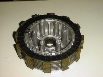
Step #4
With the nut and tabbed lock washer removed, you can now lift out the inner clutch boss, along with the entire stack of plates.
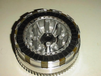
Step #5
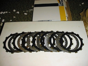
Or you can choose to leave the inner clutch hub installed, and just pluck out the plates one at a time. Which ever way you choose, you have to remove all the plates to get at the inner clutch hub. In the main stack, there are seven friction plates, and six steel plates.
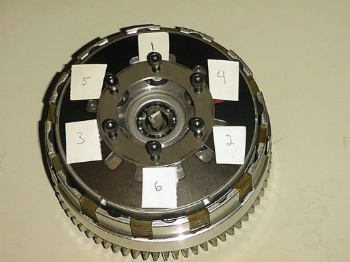
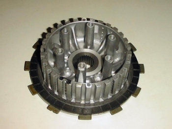
Step #6
If you choose to leave the inner hub installed while doing the work, this is what it will look like with the main stack of plates removed. At this point, you can now get at the clutch boss retaining ring.
PIC #6 Step #7
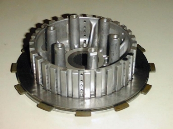
Here is a picture of the inner clutch boss, showing the steel plate, and a friction plate. They are held in place by the retaining ring, which is just visible in it's groove above the steel plate. Not visible in this picture, is the bevel spring, along with it's seat. They reside underneath the visible steel plate.
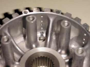
Step #8
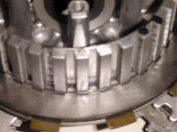
Here is a close-up of the retaining ring in it's groove.
Step #9
Here is a close-up of the ends of a properly installed retaining ring (Yeah, right...), protruding into the cavity of the inner clutch boss. Use a needle nose pliers to compress the ends of the retaining ring, and then push the ends back out through the hole. You can then carefully remove it from the clutch boss.Note: Always wear eye protection when working around your motorcycle, no matter how familiar you are with the work being performed. Accidents can always happen.
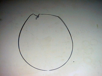
Step #10
Here Is the retaining ring, finally out of the clutch boss.
Step #11
Now that the offending object has been removed, you can now remove the last steel plate from the inner clutch boss. It is the same size as the others, and has the same part number, so don't panic if you mix it up with the other steel plates. This plate, in conjunction with the friction plate underneath it, along with the beveled spring, comprise the noise dampening assembly. Here is a picture with the steel plate removed, showing the friction plate, along with the bevel spring
Step #12
Here is the bevel spring, along with it's seat. It is called a bevel spring, because it's surface is coned. Although you can't tell from this picture, the inner diameter will be the only part of it resting on a flat surface, and the outer diameter will be above the underlying surface. If you look closely, you can just make out the word "out side" stamped in it, which is there in the hopes that the person assembling the clutch gets it right.. The purpose of the seat, is to protect the flat surface of the inner clutch boss, since the bevel spring is made of steel, and the clutch boss is cast aluminum.
Step #13
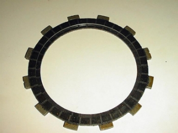
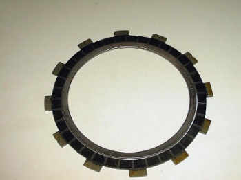
This picture shows the difference in construction of the friction plate that is part of the dampener assembly. As you can see, although it's outer dimensions are identical to the other friction plates, it's inner diameter is greater. This is so that the bevel spring & it's seat, can fit inside. Set aside the special friction plate, the bevel spring, the bevel spring seat, and the retaining ring, you will not be putting them back in.
Step #14
This picture shows the relationship of the bevel spring and the special friction plate.
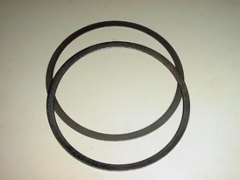
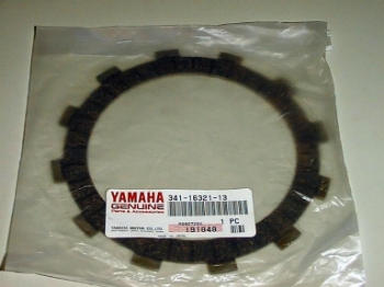
Step #15
And here is your replacement for the dampening assembly. It's another stock friction plate, that is identical to the other ones used in the clutch assembly. The part number is 341-16321-13. The special friction plate is the same thickness as the others, and although the bevel spring will rise up to a height that is slightly taller, it's compressed thickness, when added to the thickness of the bevel spring seat, is slightly less than the thickness of a friction plate. This means that it's perfectly safe to substitute a single regular friction plate, for the combined special friction plate, bevel spring, and bevel spring seat. Doing this will NOT cause any loss or increase in clutch holding pressure, or in clutch lever feel.
Final notes
Re-assembly is essentially the reverse of disassembly. Take your new friction plate, and soak it in clean engine oil for at least one hour, before re-assembling the clutch. Although it is not mentioned in the service manual, it may be a good idea to put each steel plate in with the sharp edge facing outward. As your clutch starts to wear, there will be grooves pounded in the slots of the hub & inner boss, as a result of the plates rocking back and forth when you hit the gas or let off the throttle. Over time, the sharp edges might start to hang-up in these grooves, leading to erratic clutch engagement. The steel plates are stamped from sheet stock, and as a result, one side will have smooth edges, while the other side will be sharp. I always take the time to smooth all the edges with a small file, but this is not absolutely necessary. When installing the 30mm nut, torque it to 70 Nm/50 ft. lbs. Do not forget to bend the tabs of the lock washer back up, so that the nut cannot work itself loose. When tightening the six bolts that hold the diaphragm spring in, run them in until they are finger tight, then using the same star pattern as before, tighten each bolt 1/4 turn at a time until it bottoms out, then torque to 8 Nm/5.8 ft. lbs. Although it's not in the service manual, consider giving the bolts and holes a squirt of brake cleaner, and applying a couple of drops of blue Locktite to the threads.
THANKS A LOT SANTO.
![]()
10
Swingarm bearings part #
Pay cheaper by going to a bearing store; Here are the numbers stamped on them:
Big one: IKO (brand) # TA2525Z
Small one: NTN (brand) #HMK2515
(# off my 99 swingarm)
![]()
12
Marchesini wheels bearings part #
Front wheel: SKF (brand) # 6005-2RS1
Rear wheel: SKF (brand) # 6006-2RS1 and NSK (brand) # 60/28DD-AV2S 303
Cush-Drive: SKF (brand) # 63006-2RS1